Customized Systems
MAX RF Technologies Limited provides RF test and measurement solutions, supporting systems, etc. Products include RF measurement subsystems, RF/microwave components, and customer-customized test systems.
Multi-channel RF switch network includes 4 units of 6×18 switch matrices and 1 unit of customized switch matrix (frequency range DC-40GHz) to complete the functional and test requirements of the microwave modules under test.
Case 1:

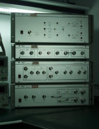
6×18 Switch Matrix Physical Unit
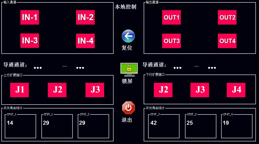
Customized Switch Matrix Channel Control Interface
- Frequency Range: DC~40GHz
- Maximum Power: 2W
- VSWR at Each Port: ≤1.3:1 DC-12GHz,
≤1.5:1 12GHz-18GHz
≤1.7:1 18GHz-32GHz
≤1.9:1 32GHz-40GHz
- Insertion Loss: ≤5dB DC~18GHz
≤8dB 18GHz~40GHz
- LAN port control with touch LCD screen for easy operation
Case 2:
Model |
Passband Range(I.L<1dB) |
Cutoff Frequency Fc(I.L<3dB) |
Stopband Range(I.L>30dB) |
Application Examples |
SFL-1 |
F1: dc-32MHz
F2: dc-190MHz
F3: dc-400MHz
F4: dc-520MHz
F5: dc-900MHz
F6: dc-1400MHz |
35MHz
210MHz
440MHz
570MHz
990MHz
1650MHz |
55-200MHz
300-800MHz
600-1800MHz
800-2000MHz
1500-2000MHz
2600-6000MHz |
HF
VHF(137-175MHz)
UHF(350-370MHz)
UHF(400-470MHz)
800MHz Trunking
GPS |
Model |
Passband Range(I.L<1dB) |
Fc(I.L<3dB) |
Stopband Range(I.L>30dB) |
Application Examples |
SFH-2 |
F1: 1.7 -3.8GHz
F2: 3.0-9.0GHz
F3: 3.4-10.0GHz
F3: 5.0-10.0GHz
F4: 6.3-13GHz
F5: 12.4-18GHz |
1.32GHz
2.70GHz
3.10GHz
4.40GHz
6.01GHz
12.00GHz |
dc-0.96GHz
dc-2.2GHz
dc-2.5GHz
dc-3.7GHz
dc-5.2GHz
dc-11.0GHz |
CDMA,GSM
DCS1800,WCDMA,TD-SCDMA
W-LAN, Bluetooth
Wi-MAX
Band C
Band Ku |
Case 3:
PM2000 Series High-Power S-Parameter Measurement System. In addition to measuring S-parameters of passive and active devices under high power conditions, the system also provides test functions that users are concerned about under high power conditions:
- √ Measure S11 of power amplifiers and passive devices at different power levels;
- √ Measure gain and gain variation of power amplifiers at different output powers;
- √ Measure S21 parameters and variations (power coefficient) of passive devices at different power levels;
- √ Evaluate temperature changes and burnout analysis of passive devices under sustained high power;
- √ Measure reverse isolation and variations of anisotropic devices (ferrite isolators) under high power conditions;
- √ Measure reverse isolation and variations of power amplifiers;
Case 4:
The 6×4/4×6 switch matrix (frequency range DC-40GHz) is designed to support Ka-band active component tuning systems and complete the functional and test requirements of the microwave modules under test.

6×4/4×6 Switch Matrix Physical Unit
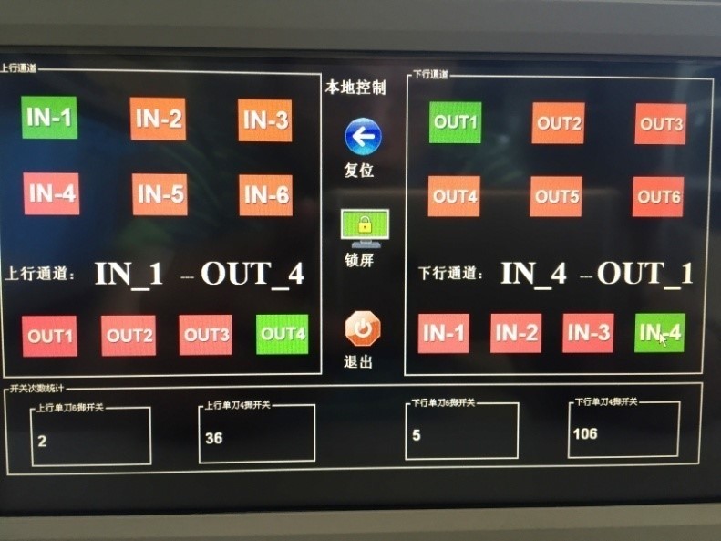
6×4/4×6 Switch Matrix Channel Control Interface
- Frequency Range: DC~40GHz
- Maximum Power: 2W
- VSWR at Each Port: DC-12GHz,≤1.6:1;12GHz-25GHz≤1.7:1 ;25GHz-32GHz≤1.9:1;32GHz-40GHz
- Insertion Loss: ≤10dB
- Phase Consistency of Each Path Before Calibration: ≤±5°@DC-3GHz
≤±10°@3GHz -6GHz; ≤±15°@6GHz -12GHz;
≤±30°@12GHz -24GHz; ≤±40°@24GHz -40GHz
- Multiple Switching Consistency for Each Channel (Same Frequency Point): Phase: ≤±10°
Amplitude ≤±0.5dB
- LAN port control with touch LCD screen for easy operation


